
House Extension and Remodelling Case Study
This article is written by Emma Thackstone. At the Detail Library, Emma helps the Detail Library with drawing new details and carrying out technical research. Emma is an Architect, who currently works on small residential projects and has previous experience of working on larger commercial projects in a medium sized architectural practice.

Detail Library resources were used extensively to support detailing. Once the construction types were decided we searched the Library for applicable references.
Case Study – 1930s Semi-Detached Extension & Remodel
In 2021, we purchased a late‑1930s semi-detached home in a quiet cul-de-sac. The house was in need of renovation, but we saw potential. It had the qualities we were looking for in a long-term family home and offered the chance to create something personal. Early sketches over the estate agent’s plans began to give us some ideas of what we might do with it.
Over the following years, we extended and reconfigured the house to improve its layout, daylighting and energy performance. This case study shares details of the process, along with technical insights and lessons learnt.
• to create a more efficient kitchen layout that was better connected to the dining area and garden
• to provide access down the side of the house (so that tools / the mower / the bins etc. could be moved from front to back without going through the house)
• to add a ground floor WC and utility room
• to future proof by allowing the house to be extended upwards in the future without changing the primary structure
• to keep some of the old features – including the high ceilings, curved plaster ceiling junction and feature artex ceiling panels (they’re nice ones, I promise)
• to keep as much of the garden as possible and to overshadow it as little as possible
• to increase the size of the first floor bathroom so that it could fit a normal size bath
• to keep some of the ground floor garage storage
Above are some key elements of the brief that we’d set ourselves
Drainage Constraints and Site Strategy
Utility searches highlighted a public drain running close to the rear of the house—confirmed by a neighbour who had encountered it during his own extension. We commissioned a drainage survey so that we could better pinpoint the location of the drain before finalising the design.
On plotting the location, we realised that we would either have to pull the extension back or push it forwards (and build over the drain) to avoid a clash between the drain and the foundations. We decided to reduce the depth of the extension to avoid the drain. The constraint meant that we wouldn’t build too far out into the garden, which we wanted to keep as long as possible due to its north facing aspect (to prevent overshadowing).
Design Development and Structural Intervention
After reviewing several options, we proposed demolishing the existing garage and kitchen extension, adding a modest but impactful side and rear extension. The existing corner of the house at ground floor was removed, allowing the new structure to wrap around and open out into the garden.
While alternative, less structurally invasive options were available, we chose this strategy to maximise spatial quality within a limited footprint. We concentrated new floor area in the kitchen, preserving the garden depth and creating a stepped elevation with increased perimeter for glazing.
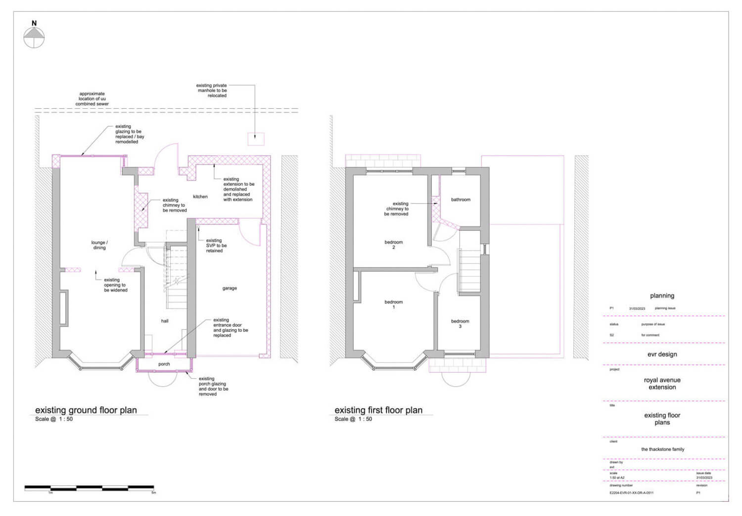
Existing floor plans marked up to show the proposed structural alterations in pink
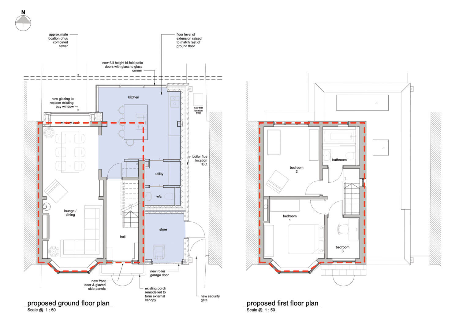
Early stage proposed floor plans with the outline of the original house shown dashed red
Glazing and Part L Compliance
The north-facing aspect allowed generous glazing without concerns about overheating. We designed full-height bifolding corner doors in the kitchen, to bring in light and blur the boundary between inside and out.
This amount of glazing exceeded the 25% floor area allowance in Approved Document Part L. The table below shows how many meters squared we would be allowed (25% of the floor area of the extension plus the area of any removed glazing). We exceeded the allowance by a couple of square meters – but we felt that the difference in the quality of light and space was sufficient for us to want to proceed with an alternative compliance route.

A table from the energy report, showing that we’d be allowed up to 14.83sqm of glazing under the Part L limitations. As we wanted more than this, we needed SAP calculations to confirm how we would meet Building Regulation requirements
Instead of following the guidance within Approved Document Part L, we had SAP calculations prepared to ensure that the extension would meet the energy efficiency requirements of the building regulations. The calculations were prepared at an early stage (before the planning application submission) to confirm that the proposal was viable. The SAP calculations confirmed that we could meet the building regulations requirements – provided that the new thermal elements of the extension met the enhanced U-Values that they’d prescribed.
Technical Drawings and the Detail Library
The drawing package included:
- Existing and proposed plans, sections and elevations
- Site plans
- 3D sketch views from Revit
- Finishes and reflected ceiling plans
- Detailed drawings (plans, sections, kitchen and bathroom)
- Setting-out drawings
Detail Library resources were used extensively to support detailing. Once the construction types were decided—e.g. 150mm cavity masonry walls, flat single ply parapet roofs, ground-bearing concrete slabs—we searched the Library for applicable references. 2D views were created from the Revit model and annotated using adapted Detail Library components. This streamlined the process and ensured consistency across the set.
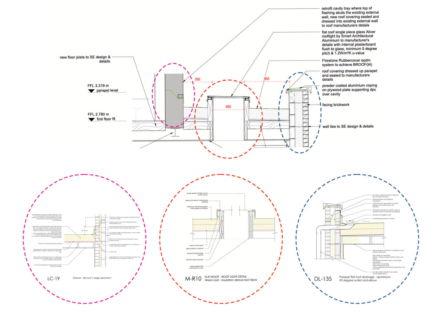
Three details from the Detail Library (shown bottom) that were used to develop the roof section details which cut through the abutment with the existing wall, the new rooflight and the new parapet
Specification Changes: Insulation
Just before construction, the contractor requested switching from partial-fill rigid insulation to full-fill mineral wool, citing buildability and time savings. We reviewed the change carefully.
Manufacturer feedback indicated the revised build-up would achieve a U-Value of 0.18 W/m²K versus 0.15 W/m²K previously. We consulted the energy assessor, who confirmed that a better-performing rooflight would compensate for the reduced wall performance.
While we accepted the change, it required significant time to update technical drawings. On a client project, such a late-stage change would have required additional fees and more formal review. A late stage performance change like this highlights the importance of communication between the Principal Contractor and the Principal Designer – to ensure the work continues to comply with building regulations and that there is sufficient time to carry out any design work.
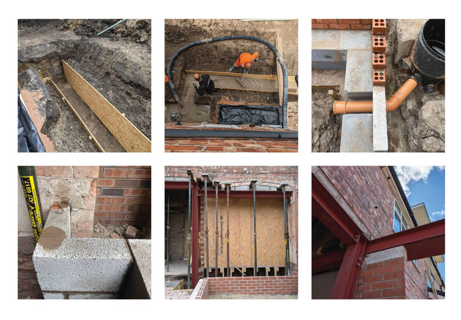
(above, clockwise from top left) timber shuttering installed to the edges of the trench foundation, concrete poured into the foundations, below ground drainage installed with a lintel where the pipe passes through the external wall, padstones installed where the new steelwork bears on to the new wall, props supporting the existing walls whilst the new steelwork is installed, wall starter tie where the new wall meets the existing wall
Ground Floor Replacement and Ventilation Strategy
Replacing the existing suspended timber ground floor with a ground-bearing slab significantly improved thermal performance. We reused crushed masonry from the garage demolition as fill and passed reclaimed timber to a neighbour’s woodworking business.
However, one potential concern that we had with this approach was the effect on the background ventilation strategy. The old floor was ‘leaky’ and allowed air to pass between the floorboards whereas the new floor is significantly more airtight. To improve background ventilation we ensured that the new glazing had as many trickle vents as possible and we also included some extra mechanical background ventilation in the kitchen area. We didn’t want the newer, more airtight elements of the house to cause unintended consequences with excess moisture.
The downside of this approach is that we lost some of the benefit of the increased thermal performance of the new envelope elements, by allowing more uncontrolled air movement. If the budget had allowed, we would have considered upgrading the thermal performance, airtightness and ventilation of the whole house (rather than just part of it) to ensure a coherent strategy and moisture safe design as recommended by BS5250.
Historically, sufficient fresh air for the building occupants and their activities was available as a result of air leakage through the gaps, cracks and openings in the building envelope; such unintentional air movement is no longer acceptable in buildings which require a heated interior because it is wasteful of energy.
BS 5250:2021 Management of moisture in buildings — Code of practice
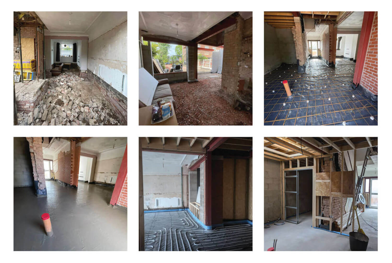
(above, clockwise from top left) removal of the existing suspended timber floor, hardcore base installed, mesh reinforcement laid above the damp proof membrane, pattress and sliding door frame installed within stud partition wall, underfloor heating pipes laid above insulation and vapour control layer, concrete slab poured
Brickwork and Soldier Course Detailing
Inspired by recent local developments, we added soldier course detailing to the facade for subtle visual interest. We traced the source bricks via planning records—Wienerberger Olde Essex Red Multi—but supply delays led us to use the Olde Cheshire Red Multi variant instead.
Brick elevations were carefully set out to avoid cuts and align soldier courses with standard coursing. Initially sceptical, the contractor later praised the aesthetic—even the inclusion of south-facing ‘bee bricks’.
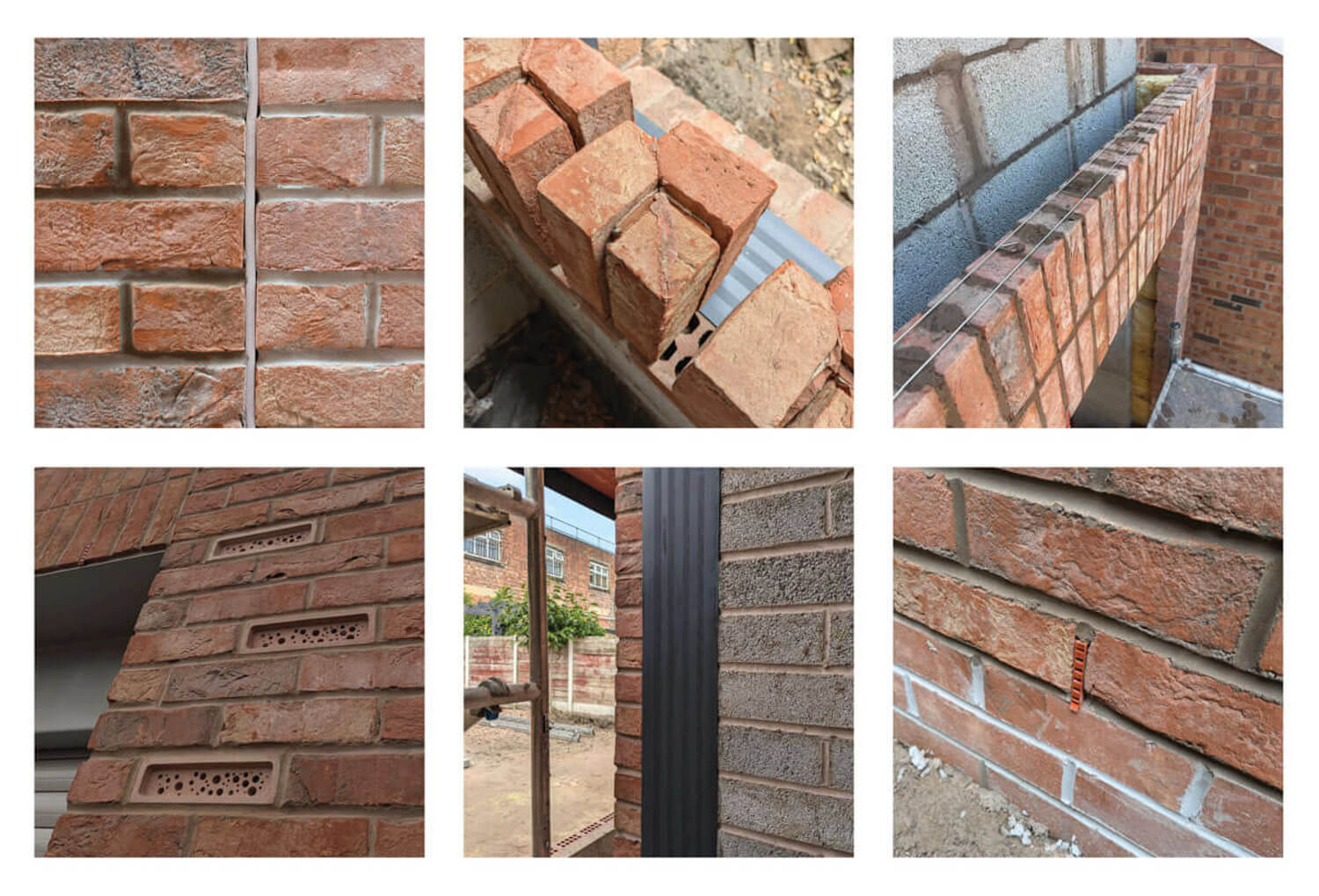
(above, clockwise from top left) movement joint installation, cut and stuck bricks for the corners of the soldier course band, soldier courses laid with bed joint reinforcement, weep hole installed above the cavity tray, cavity barrier installed at the sliding door jamb, high level bee bricks on the south facing elevation
Coordinating Corner Glazing Details
The corner bifold doors were the most complex detail on the project. Design goals included a flush ceiling line with concealed roller blinds, and floor-level alignment with internal and external finishes.
Early technical input from the glazing manufacturer helped confirm system limitations and optimal panel sizing. We incorporated the widest glazing panels that could be manufactured so that the glazing to mullion ratio was as large as possible, without having to upgrade to a more costly slim profile system.
At the head, a single steel beam supported both brick and block leaves, creating a cold bridge. We mitigated this by packing the steel web with mineral wool and overlapping the glazing with the wall insulation.
A better-performing solution would have separated structural supports for each wall leaf, but in our case, structural constraints required a single steel element. It opens up the larger question of whether we should have changed the design (to something other than corner glazing) so that we could achieve a better performing detail. In this instance we took the decision to proceed with the design – for the spatial and aesthetic qualities that the corner glazing brought to the project. We reduced the cold bridge as far as we thought possible and considered it alongside the other competing requirements of the project.
At the threshold, the blockwork inner leaf was moved outwards to support the doors, which introduced another potential cold bridge. This was reduced (but not eliminated) with perimeter insulation. In hindsight a better detail would have been to incorporate a load-bearing thermal insulation block immediately below the doors (such as a Marmox thermal block). An example of this can be seen in Detail Library detail DL-443.
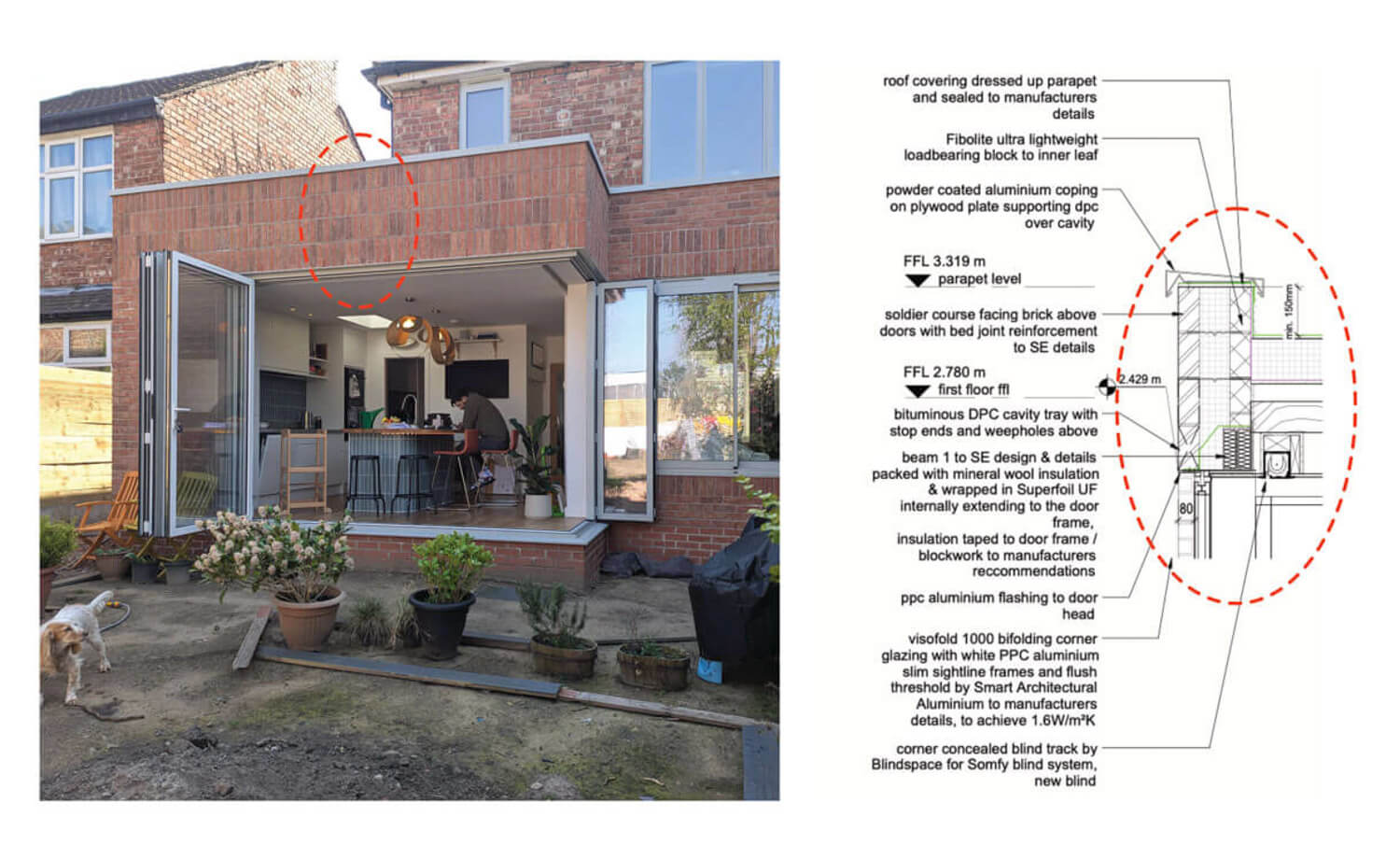
Highlight to show the head of the bi-fold doors on a photograph of the completed extension and the same junction on a section detail drawing
Future-Proofing the Structure
One of the first design decisions that we made was to set the new roof joists at the same level as the existing first floor joists. If we (or any future occupants) wanted to extend the property upwards in the future, this would allow a relatively simple build. We gained planning consent for two options – the current single storey option and a future two storey option. As we submitted both applications on the same day, we received a discount on the second application (it was effectively buy one, get one half price).
Although the two storey option was outside of the current budget, we wanted to enable a future development if there was the desire to do so in the future. We ensured that the foundations and steelwork would accommodate the addition of another storey. Remarkably only one of the steel beams had to be upgraded in size to enable this to happen. This upgrade added a small cost to the project, but would make future development far simpler and we felt it was worth it for the long term sustainability of the house.
As we progressed the design, we had to balance the desires for future proofing with the desires for the current project. We did make small compromises: winding treads in the stair improved current circulation but would need reworking in a future extension. Similarly, a structural post may need to be inserted to support glazing above the bifold corner.
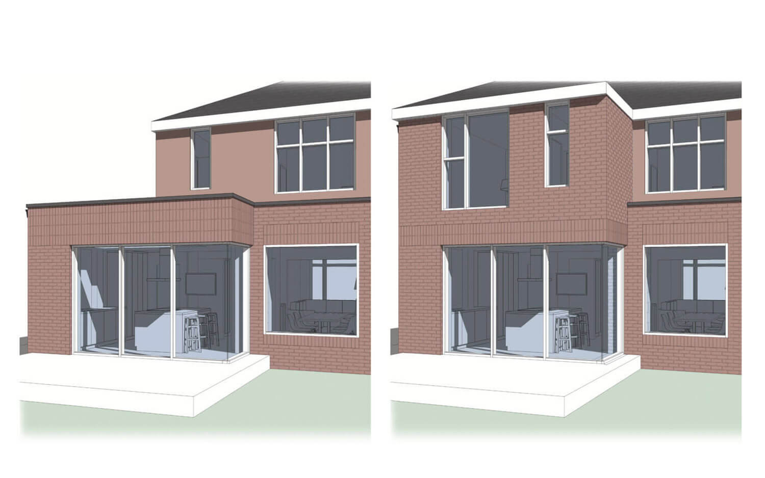
Sketch views of the two planning consented schemes; the single storey on the left and the two storey on the right
Site Learning: Abutment Detail
One element of the construction that proved problematic was the abutment detail where the new extension meets the existing house. The technical design drawings showed a new cavity tray and weep holes being inserted into the existing external wall above the knock through into the extension. This was so that any moisture that might find its way into the existing wall cavity would be funneled out through the existing wall and onto the roof before it met the new structure or internal finishes below. This is the detail required – and it should have been installed.
As works on site progressed, we realised that the cavity tray had not been included. The Contractor had not experienced retrofitting cavity trays and had not noticed that it was shown on the drawings. We agreed to monitor the situation and the Contractor (who we have a long standing relationship with) will return to incorporate the trays as soon as possible. If this was any other Client rather than ourselves, we would require this to be rectified straight away, prior to the end of the construction phase. Whilst there was no problem with the design information, in future we will take a lesson from this and will highlight the position of retrofitted cavity trays on the roof plan as well as on the section details to make it more obvious and we will discuss their inclusion before starting on site.
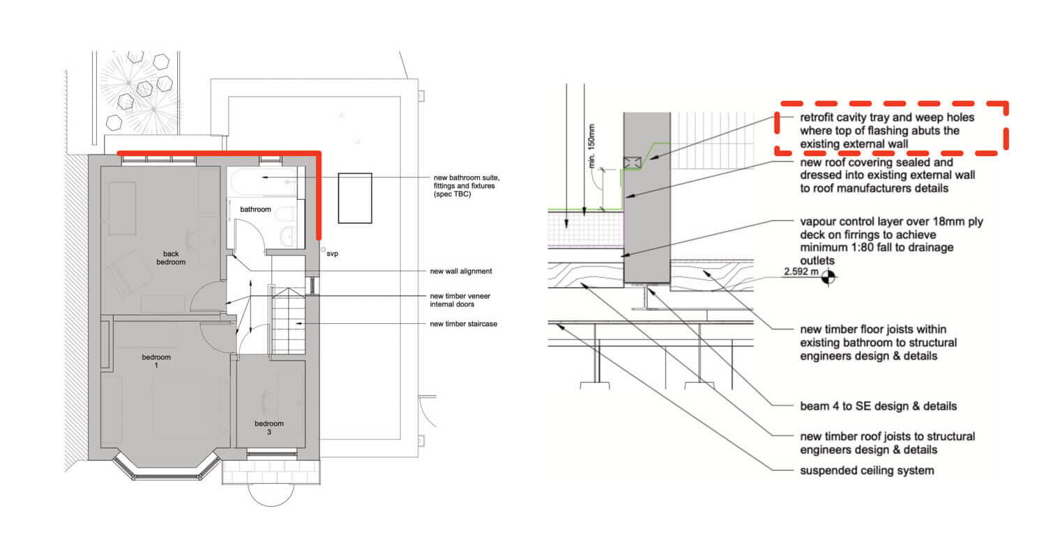
Left – a retrospective plan markup showing where the cavity tray should be located, Right – a section detail showing the abutment detail that was missed
Post-Occupancy Reflections
The reconfigured home is brighter, warmer, and more usable. Improved insulation and passive solar gain mean reduced energy use.
If we repeated the process, we’d add a utility rooflight and entrance matwell, and consider a full-house retrofit. Each project offers new insights—and working with the same contractor and engineer across jobs helps build a collective, evolving knowledge base.
Good detailing is about balancing options. Exposure to varied construction scenarios continues to inform our future design work.
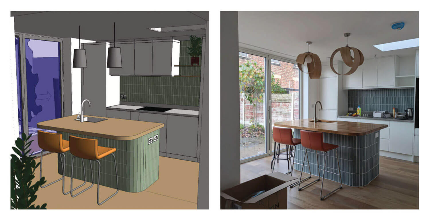
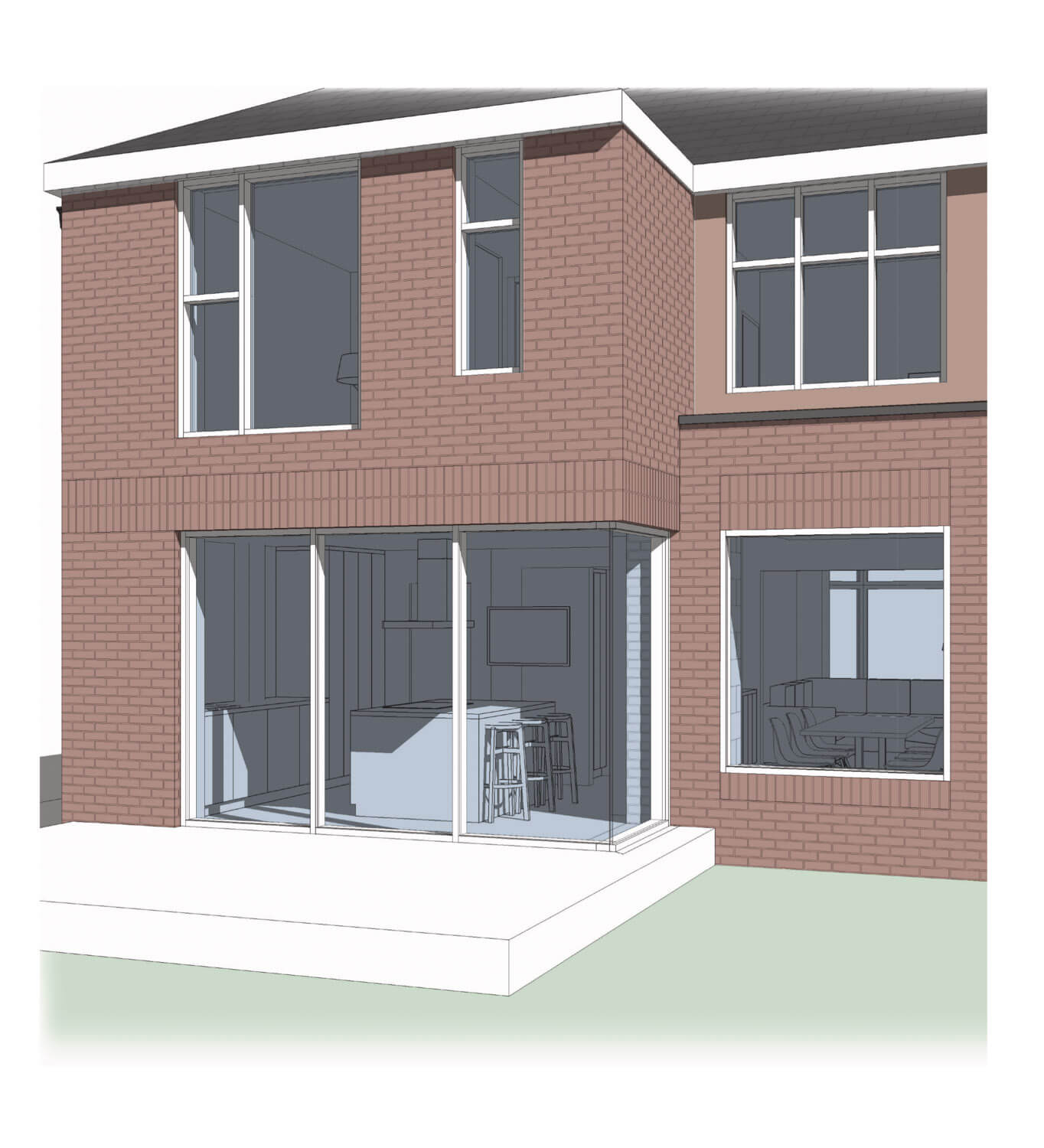
A view from the Revit model vs the (almost) finished product – modelling the extension allowed us to visualise the end result early on and helped us to identify the key details to draw and coordinate
Related Reading


Author
Written by Emma Thackstone. Emma is an architect. At the Detail Library, Emma helps the Detail Library with drawing new details and carrying out technical research.
Image Credits
All images by Emma Thackstone